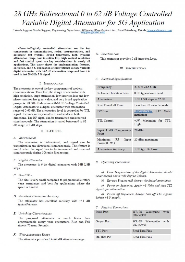
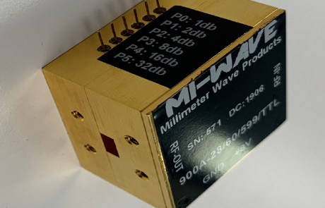
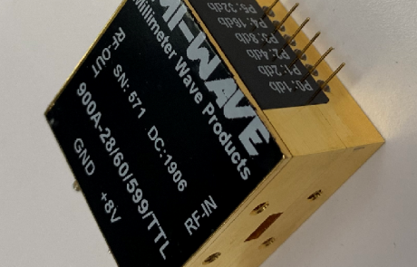
28 GHz Bidirectional 0 to 62 dB Voltage Controlled Variable Digital Attenuator for 5G Application
Abstract
Digitally controlled attenuators are the key components in communication, radar, instrumentation, and automatic test systems. Broad bandwidth, high dynamic attenuation range, low insertion loss, high control resolution and fast control speed are key considerations in nearly all applications.
This paper shows the implementation, features, operation, and 5 G application of Bidirectional voltage variable digital attenuator with 0-62 dB attenuation range and how it is used to test 28 GHz 5 G signal.
Published by:
Lokesh Saggam, Shashi Saggam, Engineering Department, Millimeter Wave Products Inc., Saint Petersburg, Florida, lsaggam@miwv.com, ssaggam@miwv.com
Contact Info:
2007 Gandy Blvd N
Suite 1310
St. Petersburg, FL 33702
Tel: 727-563-0034
Fax: 727-563-0031
I. Introduction
The attenuator is one of the key components of modern communications. Therefore, the design of attenuator with high resolution, large attenuation, low insertion loss and low phase variation has great value, and very broad application prospects. 28 GHz Bidirectional 0-60 dB Voltage Controlled Digital Attenuator is a digital attenuator with attenuation range of 0-60 dB. The attenuation level is controlled by TTL signal. It comes in very small size and works in both directions. The RF signal can be transmitted and received simultaneously. The attenuation is varied between 0 to 62 dB range in 1 dB steps.
II. Features
A. Bidirectional
The attenuator is bidirectional, and signal can be transmitted in any directional simultaneously. This feature is useful when the signal has to be transmitted and received simultaneously during 5G radio filed testing.
B. Digital Attenuator
The attenuator is 6 bit digital attenuator with 1dB LSB steps.
C. Small Size
The size is very small compared to programmable rotary vane attenuators and best for applications where the space is limited.
D. Excellent Attenuation Accuracy
The attenuator has excellent accuracy with +/-1 dB typical bit error.
E. Switching Characteristics
The proposed attenuator is much faster than programmable rotary vane attenuators. Rise and Fall time is 70 nano Seconds.
F. Wide Attenuation Range
The attenuator provides 0 to 62 dB attenuation range.
G. Insertion Loss
This attenuator provides 0 dB insertion Loss.
III. Specifications
A. Electrical Specifications
| Frequency | 27.5 to 28.5 GHz |
|---|---|
| Reference Insertion Loss | 0 dB typical over band |
| Attenuation | 1 dB LSB steps to 62 dB |
| Rise Time/Fall Time | Less than 70 nano Seconds |
| DC Bias | +8V@0.293A, +12 Volts maximum |
| TTL Control | +5V Maximum for TTL High |
| Input 1 dB Compression Point | 20 dBm |
| Maximum RF Input Power (C.W.) | 25 dBm maximum |
| Attenuation Accuracy | 1 dB typ. Bit Error |
B. Operating Precautions
a) Case Temperature of the digital Attenuator should never exceed above +60 degree Celsius.
b) Reverse Biasing will destroy the digital attenuator.
c) Power on Sequence: Apply +8 Volts and then TTL signals per attenuation.
d) Power off Sequence: Always turn off TTL signals before +8 V supply.
C. Physical Dimensions
| Input Port | WR-28 Waveguide with UG-599/U |
|---|---|
| Output Port | WR-28 Waveguide with UG-599/U |
| TTL Port | Feed Thru Pins |
| DC Bias Pin | Feed Thru Pins |
| Material | Aluminum |
| Finish | Gold Plated |
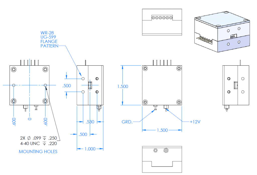
| Size | 1.5”X1.5”X1.5” |
| Weight | 2 Ounces |
D. Truth Table
| P5
32 dB |
P4
16 dB |
P3
8 dB |
P2
4 dB |
P1
2 dB |
P0
1 dB |
Attenuation State |
|---|---|---|---|---|---|---|
| High | High | High | High | High | High | Reference Insertion Loss |
| High | High | High | High | High | Low | 1 dB |
| High | High | High | High | Low | High | 2 dB |
| High | High | High | Low | High | High | 4 dB |
| High | High | Low | High | High | High | 8 dB |
| High | Low | High | High | High | High | 16 dB |
| High | Low | Low | Low | Low | Low | 31 dB |
| Low | Low | Low | Low | Low | Low | 62 dB |
III. Implementation
Outline Drawing
IV. Application
• Fiber Optics & Broadband Telecom
• Microwave Radio & VSAT
• Military Radios, Radar & ECM
• Space Applications
• Sensors
• Test & Measurement Equipment
• 5G Radio Field Test

How to Order & Custom Products
As the manufacturing source, we have top sales engineers ready to answer all your questions and quote you on product needs. You’ll find our prices are some of the best since we manufacture all our millimeter wave products in house.
Have a custom job or unique need? No problem! Contact us so we can work on solutions to meet your needs.
2007 Gandy Blvd N
Suite 1310
St. Petersburg, FL 33702
Tel: 727-563-0034
Fax: 727-563-0031
Email: sales@miwv.com

